Configuring Pan/Tilt Limits (G3 & G2 Cameras)

Configuring pan/tilt limits allows you to limit the pan and tilt range of the camera. This is useful for limiting the camera’s observable area. For example, in a live broadcast stage play, it may be useful to limit the camera's pan range to the left and right ends of the stage, and limit the camera’s tilt range to the highest and lowest parts of the stage. This prevents the cameras from being accidentally turned around to face the audience, and generally limits the camera to show only what’s intended to be shown.

Pan/Tilt Limits
Pan/tilt limits can be applied to a camera using legacy applications such as the Camera Management Platform, the 1.4.1 control app, using VISCA commands, or from the Horizon web interface on Move 4K cameras. Continue reading to learn how to set pan/tilt limits, and how to clear them.

Setting Pan/Tilt Limits (G3 & G2 Cameras)

Use the methods below to set pan tilt limits.

Note: Follow these instructions to enable the Horizon web interface on your Move 4K camera: Accessing Horizon | PTZOptics

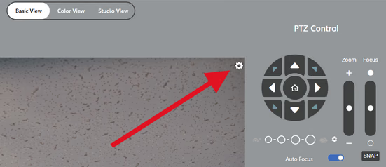
  1. From the Basic View of the Horizon interface, click on the settings cog in the top right of the stream preview.
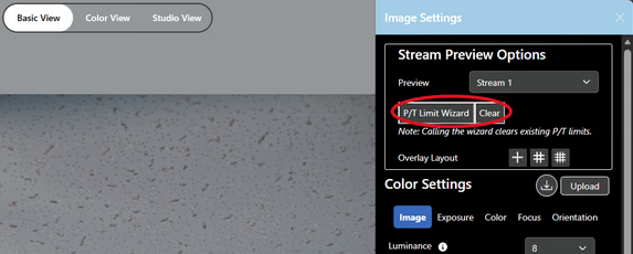
  2. From ImageSettings, click on P/T Limit Wizard to start the wizard. Note that starting the wizard will clear any currently set limits. You can also clear pan/tilt limits by clicking the Clear button on this page.
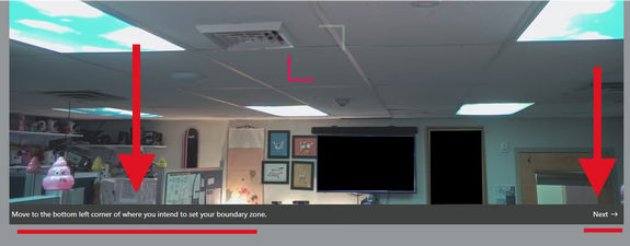
  3. Follow the instructions at the bottom of the stream preview to finish setting the cameras’ pan/tilt limits. You’ll be asked to move the camera to the bottom left and top right limits before hitting next to save each boundary.
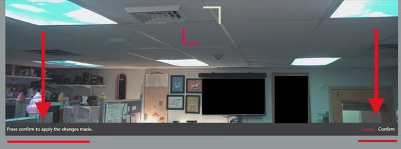
  4. Once both boundaries are set, click Confirm to apply the boundaries and finish setting pan/tilt limits.

Setting Pan/Tilt Limits with Packet Sender (Advanced)

You can find the full list of VISCA commands for G3 and G2 cameras here: PTZOptics Developer Portal . Download and install Packet Sender from https://packetsender.com/download. You can also download this Packet Sender database which includes all of the commands used in this guide. Import the database within Packet Sender from File > Import Database.

Here are the commands we will be using to set pan/tilt limits:

CommandFunctionCommand PacketComments
Pan_TiltLimitSetLimitSet81 01 06 07 00 0W 0Y 0Y 0Y 0Y 0Z 0Z 0Z 0Z FFW: 1 (UpRight), 0: DownLeft YYYY: Pan position, ZZZZ: Tilt position
*LimitClear81 01 06 07 01 0W 07 0F 0F 0F 07 0F 0F 0F FFW: 1 (UpRight), 0: DownLeft YYYY: Pan position, ZZZZ: Tilt position

Packets should be sent to the camera’s IP address using UDP on Port 1259 as pictured below. Enter your camera’s IP address in the Address field. Note: The UDP server within Packet Sender may be disabled by default. Enable it before sending commands by clicking on the UDP server button at the bottom of the interface.

  1. Adjust the camera to the upper right limit of the intended boundary zone.

  2. Within Packet Sender, select the Pan/Tilt Inquiry command (81 09 06 12 ff). The HEX field will populate with the command. Click Send. This command will prompt a response from the camera that will return the camera’s current pan/tilt coordinates in the log section, boxed in red below.

  3. Note the green-highlighted coordinates in the example response below.

    Pan Tilt Inquiry Response
    90500001070500000f0aff
    Coordinates
  4. Prepare the pan tilt limit set command (81 01 06 07 0x 01 00 00 00 00 00 00 00 00 ff).

  5. Replace the green-highlighted characters with the coordinates obtained from the inquiry response, then send the command. Below is an example of the pan tilt limit set command with

    Pan Tilt Limit Set Command
    81010607000x0001070500000f0aff
    Up-Right (01) or Down-Left (00)Coordinates
  6. Attempt to move the camera past the set upper right limits to confirm the limits are set.

  7. Repeat steps 1 through 3, adjusting the camera to the lower left limit and using the Down-Left designation in the pan tilt limit set command, as pictured above.

Camera Management Platform (CMP)

You can download the Camera Management Platform here: The PTZOptics Camera Management Platform - PTZOptics Note: Pan/tilt limits can only be set on cameras added to the CMP using a network connection; pan/tilt limits cannot be applied to USB (UVC) connected cameras. If you’re unable to connect your camera to the CMP, check out this troubleshooting guide.

Note: This application is prone to bugs, so the “Done” button in the PT Limit Helper prompt may not work. This can happen regardless of operating system or camera generation. Consider using other methods.

  1. You can set pan tilt limits from the PTZ Control menu pictured below.

    CMP

  2. Click on “PT Limit Helper” and follow the on-screen instructions to set pan-tilt limits.

  3. Move the camera through the pan/tilt range to confirm where the limits have been set. Click on the red “x” to the right of “PT Limit Helper” to clear the selected camera’s pan-tilt limits.

1.4.1 Desktop Control App (Legacy)

You can download the desktop control application here: Free Camera Control App Download for PC and Mac - PTZOptics

Note: It is possible to use this application to set pan/tilt limits from Settings > Pan/Tilt Limit Setting, but it will not allow you to set a right limit in the left hemisphere or a left limit in the right hemisphere, only one pan limit per hemisphere. This behavior is consistent across G3 and G2 cameras. Consider using other methods.

Clearing Pan/Tilt Limits [G3 & G2 Cameras]

Use the methods below to clear pan/tilt limits.

IR Remote Command (Move SE Only)

  1. Aim the remote at the camera and press the "P/T RST" button to clear the camera's pan/tilt limits. The camera will pan/tilt to recalibrate when the command is received. Note: This command will not work on the Move 4K. The camera will move through its calibration motion, but the limits will not clear.
  1. Open the OSD menu using the MENU button in the web interface, or using the MENU button on the IR remote. (Menu > Restore Default > P/T Limit Reset? Yes > Enter/Home)

HTTP Command (Move SE & G2 Cameras (NDI/SDI))

You can find the full list of available HTTP commands here: PTZOptics Developer Portal for PTZ cameras Note: If HTTP authentication is enabled on the camera, you will need to provide the camera's admin credentials when using this method.

  1. Use the HTTP command /cgi-bin/param.cgi?pan_tiltdrive_reset to clear the cameras’ pan/tilt limits.
  2. Type the camera's IP address before the command in your browser. If the command is successful, you’ll receive the confirmation message shown below.
  3. If you’re prompted for credentials, enter the camera's admin credentials. If you receive a 401 authentication error, the credentials used were incorrect.

Clearing Limits via Packet Sender (Advanced)

You can find the full list of VISCA commands for G3 and G2 cameras here: VISCA API | PTZOptics. Download and install Packet Sender from https://packetsender.com/download. You can also download this Packet Sender database, which includes all of the commands used in this guide. Import the database within Packet Sender from File > Import Database.

Packets should be sent to the camera’s IP address using its current UDP port. The camera’s default UDP port is 1259. Enter your camera’s IP address in the Address field. Note: The UDP server within Packet Sender may be disabled by default. Enable it before sending commands by clicking on the UDP server button at the bottom of the interface.

  1. Using Packet Sender, send the Pan\Tilt Limit Clear commands.

  2. Pan\Tilt Limit Clear Command (Up-Right) (81 01 06 07 01 01 07 0f 0f 0f 07 0f 0f 0f FF).

  3. Pan\Tilt Limit Clear Command (Down-Left) (81 01 06 07 01 00 07 0f 0f 0f 07 0f 0f 0f FF).

  4. Note that the camera will not move through its pan/tilt startup dance when receiving these commands, but the limits will clear. You should also receive confirmation packets back from the camera.

  5. Up-Right Clear Confirmation Packets: (90 42 ff) (90 52 ff)

  6. Down-Left Clear Confirmation Packets: (90 41 ff) (90 51 ff)